When i started this project i was very confident about how easy the process would be to just put big LiPo cells on an existing DJI Battery controller. But by walk-in the subject i discovered the reality and complexity of managing electrochemicals cells. This black magic called gas-gauging obligated me to found a way to solve and achieve my project. At the end it teached me a lot on many points, then the knowledge i’ve been able to accumulate here will be helpfull for my future hacks. I hope it could also help others users of DJI UAV and electronics enthusiats in the future by the documentations synthetized here.
Introduction
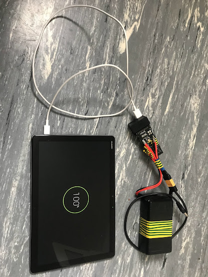
Long short story, i’m the happy owner a DJI Mavic Pro UAV, first of the name. This quadcopter come from the shop with a bunch of accessories, like for example adaptator to use the batteries as USB powerbank. By spending a lot of time off-grid in my van so this kind of functionnality are usefull for me.
Later, the hasard of life, put a bunch of large LiPo cells on my road for almost no cost due to a malfunctionning of their electronics controllers. i’ve searched a way to reuse them to build a large multipurpose battery pack for all my devices like my TS100 soldering iron for exemple.
DJI Mavic Pro Battery
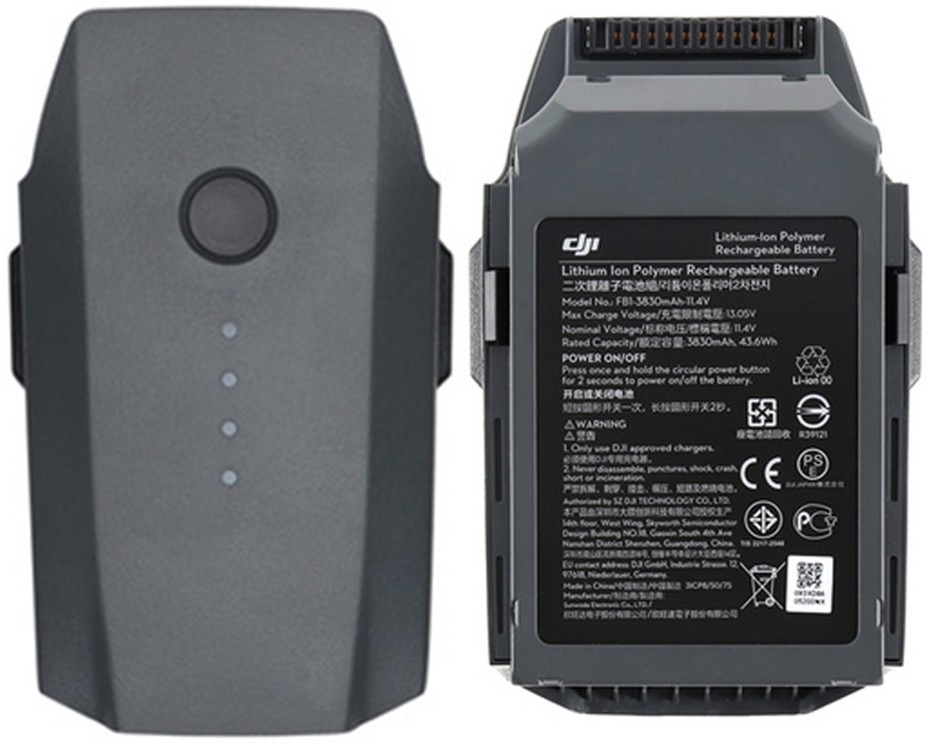
Aka known as the DJI Intelligent Flight Battery, it’s basicly a 3S 11.4v Li-Po of 3830mAh, made of H.V cells.
The battery itself contain an electronic board with built-in sensors and bright LEDs that help you to known the state and the remaining power of the pack. Features are present like automatic discharge for preserving the cells, but also security systems can act as a virtual fuse in case of irreversible damage or unexpected behavior of the battery pack.
In other terms, this kind of battery has smart features to extend their life and made them very safe. That’s great, and that make me want to benefit of thoses features for my own DIY pack. So, that’s why i have bought a dead cell DJI battery on internet with the goal of reuse the electronics inside.
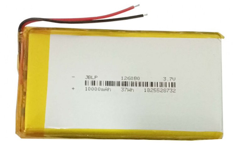
My Bunch of Li-Po cells
No much to said, my Li-Po cells come from dead usb powerbanks where the electronics controllers was too much cheap and was malfunctionning. They are 10.000mAh, 3.7v regular pouch cell’s.
Componants Overview
At start, my goal was to just bring together 3 large Li-Po pouch cells and solder them to the smart DJI Mavic Pro battery controller, then.. that’s all !
But it didn’t goes as expected. Let’s digg in ..
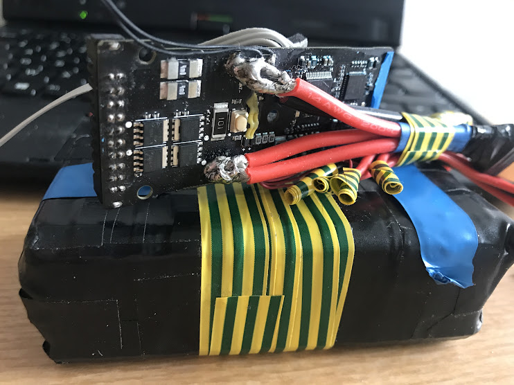
Once oppened, the battery is made three part :
- A main controller board, (below) with connectors, micro-controllers, sensors, leds status, button.
- A second power board who’s put cells in serie, bring power and balances cables to the main board.
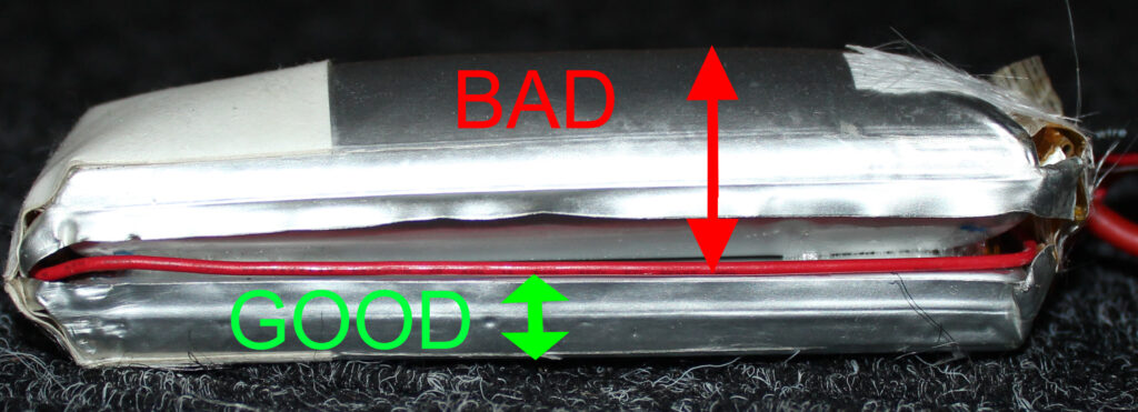
- Then the cells themself, three 3800mAh, 3.7v H.V Li-Po pouch cells.
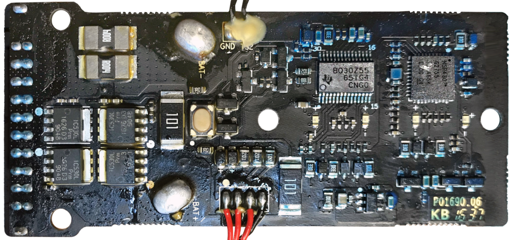
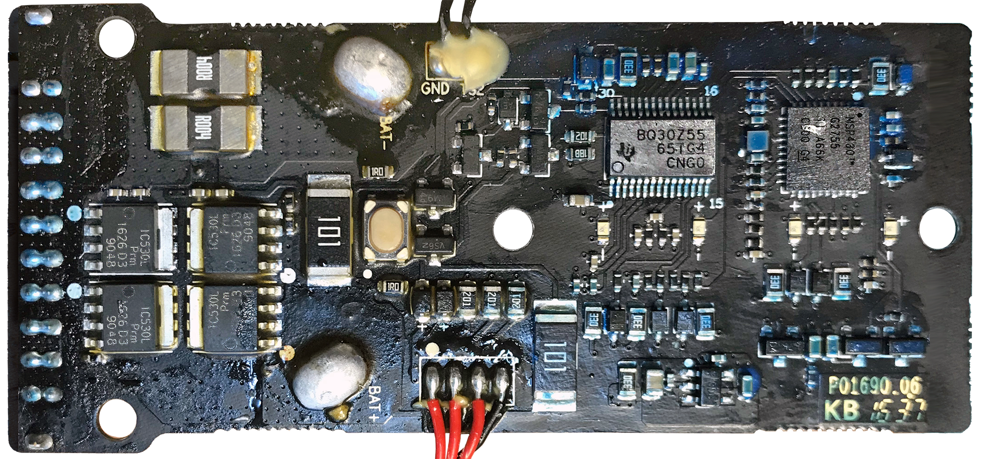
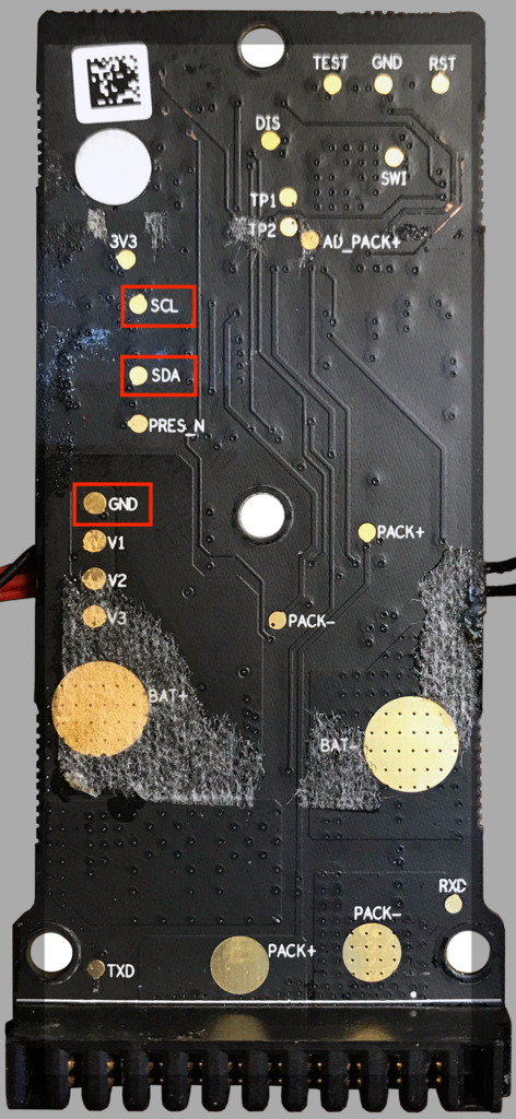
On this picture upper, we can see many elements of the board controller , from the left to the right :
- The DJI connector used to interact with devices from the brand.
- The two big pin BAT+ and BAT- obviously connected to the 11.4v LiPo 3S pack.
- In the center we found a push-button to on/off the board followed by 4 LEDs.
- On top we have two black cable who are related to the temp sensor.
- On the under, we found four cable, related to the balance between cells.
- A BQ30Z55 Texas Instrument micro-controller chip, it contain all the intelligence of the board.
I’m not gonna explain how to soldering the cells in serie together and the JST balance cable to the board, but you can refering to the diagram connexions below :
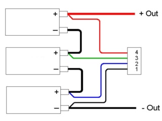
Workaround with the Intelligent Board
At that point i balanced and soldered the cells together, then to the controller board. But the pack was actually not working.. I was naively thinking that replace the cells will simply fix the whole battery. But i was unable to drain power or recharge the pack throught the DJI board with the wall charger. The leds was blinking, but akwardly.
This is where many DJI Mavic Pro UAV pilot could be interested. By digging deeper into how work BMS controllers i discovered more and more about the security feature of DJI batteries and how we can fix them but also regrogram them to goes in our way.
It was not intended in this project, but encountering thoses problems teached me a lot about gauges controllers, the protocols they uses and how hack them for low cost insteed of buy new pricey packs.
I must mention that opening a battery is obviously not safe and should be done very carrefully..


Deal with the Permanant Fail Flag
Before in this article i have explain that the smart board controller contain some inteligence. A Texas Instrument BQ30Z55 here. This chip pilot the whole system, including security features to protect the battery before causing any dammage by burning or exploding for example. But also by preserving the UAV of outage during flight.
Things are very well done, the micro-controller check permanently the cells, by regarding temps, voltages, internal resistance and disbalance bewteen cells. Then if the health of the battery pack is too much degraded the controller will decrete that the pack is now representing a risk. Or would not be anymore suitable for the tasks they have been designed they will switch into a secure state called « Permanent Fail ». After that, the controller will stop delivering power and will also not allowing recharge.
The symptoms
You still can start and stop the battery, but you no longer get power delivered, the UAV doesn’t start at all.
When the battery is plugged to a wall charger, the leds will goes blinking up normaly. But few seconds later (only after few rise) the leds will stop completely for few seconds.. Then start blinks rise again like if it was loading.. This will made an infiny loop and will in reality never recharge.
At this point it’s more than probable that the battery controller is entered in the Permanent Fail this state is also called « PF Flag » frequently. It mean that the pack has encountered something bad.. The most of the time, only one of the three cells are dead.
So if you are adventurous and lucky, the repair of your DJI Mavic battery could only cost you the price of one 3800mAh H.V Li-Po cell. Instead of a brand new battery. But if you change the cells i recommand to change the three together.
The only sad fact about this security feature, is that if you fix the cell problem, the battery will not just go back online herselft. After it’s switched to PF state it’s like forever .. or maybe not like how we will see it later 😉
What we need now is going deep in the rabbit-hole of micro-chip reprogrammation to unlock the controller board.. Don’t worry it’s not that’s complicated as it sound.
Perhaps you will need somes minor IT and soldering skills to walk throught this.
Fix the PF state issue
Important ! As i mentionned before, if the battery pack is entered in Permanant Fail mode it’s because something not good happened. If the source of the problem is not fixed at least the pack will very soon go back in the PF state.. if you are lucky. But you could also risk to overlap the intended safety role.. and fireworks are more fun when they’re not in your hands and face, don’t you think ?!
Got it ? Ok, let’s go !
In our case the micro-controller chip is a Texas Instrument called BQ30Z55, you can found here is the datasheet for more details if needed : BQ30Z554-R1 Datasheet Others controller docs can also be easily finded on internet. But almost all the controller work in the same way with the SBS protocol.
According to the documentation many reasons can lead to this state :
Protections Safety Features

The bq30z554-R1 supports a wide range of battery and system protection features that can easily be configured. The Protections safety features include:

• Cell Undervoltage Protection
• Cell Undervoltage I*R Compensated Protection
• Cell Overvoltage Protection
• Overcurrent in Charge Protection 1 and 2
• Overcurrent in Discharge Protection 1 and 2
• Overload in Discharge Protection
• Short Circuit in Charge Protection
• Short Circuit in Discharge Protection 1 and 2
• Overtemperature in Charge Protection
• Overtemperature in Discharge Protection
• Overtemperature FET protection
• SBS Host Watchdog Protection
• Precharge Timeout Protection
• Fast Charge Timeout Protection
• Overcharge Protection
• Overcharging Current Protection
• Overcharging Voltage Protection
• Instruction Flash
• Open Cell Tab Connection
• Data Flash
To be brief, in our Permanant Fail case, the memory of the micro-controller contains a flag called Permanent Failure, This flag has been triggered by the controller because one of the cells was swolled. The flag should be set as « 0 » Inactive when the battery work well. But switched to « 1 » Active if dead.
There is multiple softwares and hardwares to work with Texas Instrument battery controller, but the way will still remain the same. The controller is protected from external modifications in a state called sealed, so it will be needed to unseal it before be able to perform a PF reset or any others wanted modifications like reset the cycle counter for exemple. One finished, re-seal it.
In all the case you will need a decidated device to talk to the battery controler because regular computer does not provide interface to communicate over the SMBus protocol with the micro-chip. fortunally SMBus are derivated from I2C and mostly compatible witht it.
Available Hardware & Software tools :
- EV2300/2400 device Genuine or clone, dedicated to Texas Instrument chip with BQ Studio.
- Raspberry PI combinated with comm_sbs_bqctrl.
- Arduino Boards With somes github projects.
- CP2112 or equivalent I2C/SMBus usb interface for computer. combinated with DJI Battery Killer.
The SMBus protocol is what we will need to use to communicate with the micro-controller, fortunally for us, the SMBus is derivated of and mostly compatible with it. Again it’s a luck, because devices like Raspberry PI or Arduino are able to use their native I2C interface, and that’s what we are gonna use.
The process is already explained in the first part of this video succeded by the Raspberry method.
Like me, it’s highly probable that you did not possess EV tool or CP2112 module.. Hopefully Raspberry are way more foundable around you and will be suffisant in the majority of case (Only reset the PF flag).
Setup the RaspberryPI
You will need to setup an installation of Raspbian or any other usable Linux based system for the Raspberry board. You can follow the install guide on their official website if needed.
After you booted you must config few I2C parameters.
Editting the boot config parametters :
sudo nano /boot/config.txtSet or activate thoses parametters for the I2C interface :
dtparam=i2c_arm=on
dtparam=i2c_baudrate=66000
dtparam=i2cl_baudrate=66000
dtparam=i2c_arm_baudrate=66000
Reboot your Raspberry ..
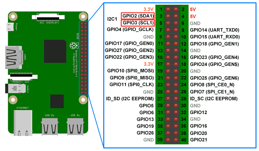
You need now to wiring the DJI board with the I2C interface of the Raspberry PI.
You can follow the diagrams below where the both boards pinout show how-to achieve the I2C/SMBus connexion. Follow this video if not perfecly clear.
Establish contact with the BQ30Z55 Controller
To prepare the software environnement on the Rapberry PI, we needs to get the communication tool program called comm_sbs_bqctrl.py present in the dji-firmware-tool repository of O-GS for later.
Download the communication and reprogramming tool from the O-GS Github repository :
wget https://github.com/o-gs/dji-firmware-tools/archive/refs/heads/master.zipExtract and going in the directory :
unzip master.zip && cd dji-firmware-tools-masterMake sure the software tool we gonna use is well executable :
chmod +x comm_sbs_bqctrl.py Install the SMBus2 protocol module for Python :
pip3 install smbus2Now try to detect the BQ30Z55 throught the I2C wiring :
i2cdetect -y 1You should get something like this :
    0  1  2  3  4  5  6  7  8  9  a  b  c  d  e  f
00:                         -- -- -- 0b -- -- -- --
10: -- -- -- -- -- -- -- -- -- -- -- -- -- -- -- --
20: -- -- -- -- -- -- -- -- -- -- -- -- -- -- -- --
30: -- -- -- -- -- -- -- -- -- -- -- -- -- -- -- --
40: 40 -- -- -- -- -- -- -- -- -- -- -- -- -- -- --
50: -- -- -- -- -- -- -- -- -- -- -- -- -- -- -- --
60: -- -- -- -- -- -- -- -- -- -- -- -- -- -- -- --
70: -- -- -- -- -- -- -- --
if everything is ok you can go further, if not, get help, check your wiring twice etc..
Read and Rewrite the BQ30Z55
My Raspberry PI Shell during the process :
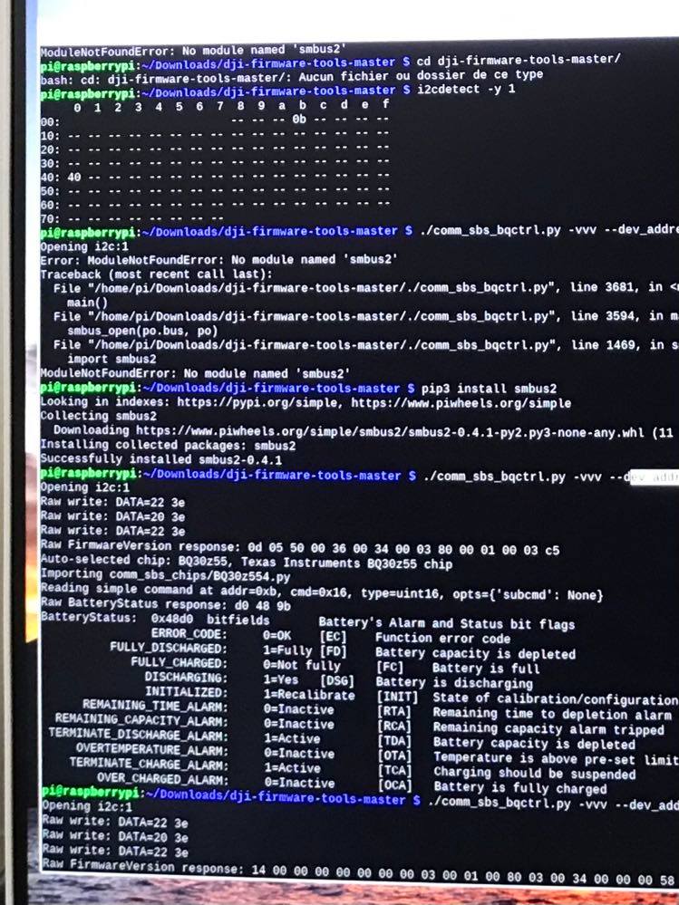
Now we gonna do the first read of the micro-controller throught i2c :
./comm_sbs_bqctrl.py -vvv --dev-address 0x0b read BatteryStatusYou should now be able to read few details about the status of the battery controller state.
Now we are going to unseal the controller to allow us to reset the PF Flag :
./comm_sbs_bqctrl.py -vvv --dev-address 0x0b sealing UnsealYour battery controller is now editable, and the return of the command should show you :
PERMANENT_FAILURE: 1=Active [PF] Permanent FailureNow reseting the PF flag state :
./comm_sbs_bqctrl.py -vvv --dev-address 0x0b trigger ManufacturerAcces.PermanentFailDataResetIf it’s a success, congrats your controller is now back online,
The last part is to reseal the controller before quit :
./comm_sbs_bqctrl.py -vvv --dev-address 0x0b sealing SealThe return of the command should now show you this instead :
PERMANENT_FAILURE: 0=Inactive [PF] Permanent FailureYou can now disconnect all the wire. At this is point, the battery pack should working like a charm..
For me all was working as expected now. I was able to recharge and use the battery pack in my Mavic Pro or as USB charger with the DJI accesories.
Go further in the Battery world
Working on this project make me discover that Texas instrument was the main leader of the battery gauge market. But also that some standard exist for communicate with thoses controllers.
When digging around the PF state of my pack, i was surprised of how many usefull data was available and displayed on my computer and how it would be interesting to visualize them in the field.
By thinking a little, i remembered that Atmega based devices like Arduino or ATtiny device also possed an I2C interface, so i made research about how to read thoses data directly throught them to maybe have an embed data reader on the pack.
By luck i founded Github’s repository using different methods to rewrite my own data extract tool. There is the result i was able to get :
====== Global Data ======

Manufacturer Name: ATL  NVT
Manufacture Date: 2018-10-15
Device Name: DJ008
Serial Number: 1671
Chemistry Type: LION

Specification Info: 49
State of Health: 49

Design Capacity: 1915 (mA)
Current Capacity: 1831 (mA)
Design Voltage: 11400 (mV)

====== Charge Data ======

Max Charging Current: 2000 (mA)
Max Charging Voltage: 13050 (mV)
Cycle Charging Count: 14

====== Battery State ======

Battery Mode: 0b110000000000001 (Bin)
Battery Status: 0b11000000 (Bin)

====== Dynamics Data ======

Temp: 20.45 °C

Main Voltage: 11.72 (V)
Remaining Capacity: 1133 (mAh)

Cell 1 Voltage: 3900 (mV)
Cell 2 Voltage: 3904 (mV)
Cell 3 Voltage: 3915 (mV)

In/Out Current: -59 (mA)

Relative Charge: 62 (%)
Absolute Charge: 60 (%)
Full charge remaining time: -1 (Min)If it’s not actually the case when you are reading this, i will soon publish my code on github to reproduce this data reader for the SBS protocol based battery pack. Be patient. Hello Github 😀
Second Round of Reprogramming
A step further .. Working with the SBS Protocol to get datas with Arduino on my battery pack make me realise that somes parametters like the DesignCapacity() or the DesignVoltage() was now not longer adapted to my custom battery..
The two main reason is that i have put cells with 2.6x more capacity but also because they are regular cells and not HighVoltage one (H.V) like the genuine so they don’t support 4.35v per cells but only 4.20v.
This will actually put the controller in wrong dispositions to manage the pack because the whole process is mainly a predictive algorithm over the chemical reaction, tunned by the value you set to match your pack.
To solve this i must edit somes values wrote deep in the BQ30z55 controller memory. To achieve that, i will present two method.
The one use the DJI Battery Killer tool on Windows throught a CP2112 USB to SMBus module to interface the BQ30z55 chip to your computer. This is the easy way but costly due to the module.
Then the second will use a combinaison of two opensource soft, one on Raspberry and the second on Arduino.. Combine them both on raspberry should be possible and preferable i think.. Next project ?!
So you need to possed both Arduino An Pi for the moment .. This is still my favorite method because you use opensource codes, use « common » electronics device, mostly easily available, then you really understood what you are doing.
DJI Battery Killer Method
First you need to get a CP1212 USB to SMBus module.. Actually around 50$ .. Crazy period.


Like explained before, about the Permanant Failure unlock upper in this article, connect SDA, SCL and GND between the CP2112 and your battery.
Next, you need to download and run the DJI Battery Killer software, actually it’s not opensource, no warranty about this soft, no official website, no official release.. There is a working copy attached.
Connect .. Read .. Unseal ..
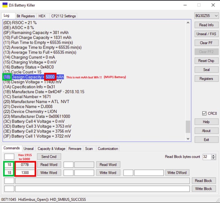
Here after reading global infos and unsealing the chip i specificly read the 0x18 value known simply as 18 or DesignCapacity() .. The default value for my battery pack is 1915, this value represent the global capacity of the pack but not in common mAh representation but instead in bunch of 10mWh.. Quite uncommon yeah !?
That’s actually because my controller chip is set to CAPACITY_MODE = 1 by the manufacturer.
By the way, after undestanding that you also must known that the value is stored as hexadecimal value, so 1915 = 077B, that mean if you want to rewrite a value, set it back as a hex one.
Did you get that.. 1915 x 2 is exactly equal to 3830(mAh) 😉
So to match my case where i changed the cells from 3830 to 10.000 mAh the proper value to set would be around 5000 bunch of 10mWh. In hexacimal that represent 1388. As you can see upper..
Next in my case i’ve put regular lithium cells insteal of highvoltage one.. so the DesignVoltage (0x19) should not be 11400(mv) but 11100(mv) instead .. Same process as before allow you to down the voltage.
If you don’t change this last value on regular cells the controller will still try to charge them at 4.35v
After done, Reseal .. Disconnect .. Goodbye 😉
OG (Tools) and the Cockroaches ..
Hope you get the joke .. To perform the exact same as explain before for the DJI Battery Killer solution you will need to combine the O-GS Tools comm_sbs_bqctrl.py and DSA Smart Battery Arduino solution.
I’ll be a little bit expeditif on this second approch because it’s improvable and i will probably edit it later.
- O-GS Tools, comm_sbs_bqctrl.py will unseal/reseal the controller but will not be able to edit values.
- The DSA Smart Battery project will edit values but does not unseal or seal chip controlers.
So first unseal it with the comm_sbs_bqctrl.py tool with a Raspberry PI, the trick is explain upper in the PF Flag section.
Second, unplug the battery controler from the Raspberry Pi then connect it to an Arduino to edit values by following the logic explained before.
Then at the end replug it to the Raspberry if you want reseal the chip. Personnaly i let it unsealed ✌️
A little check of the cells drift (below 0.03v) over discarge :
Adding electronics is funnier
Every step in this project make me learn a lot … fooling around with the chip reprogrammation and arduino make me realise how much data was available.. But obviously not for regular users.
For exemple, almost all RC pilot use dumb Li-Po battery pack without BMS, so they need specials chargers, and devices to control the balance and the health of theirs packs. In our case the controller board pilot the charge and discharge, get and store all the precious data. This allow to substitude thoses external devices.
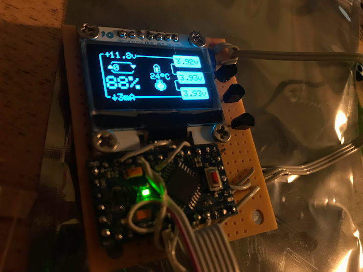
That’s how i get the idea to embeded an Arduino Micro with a small screen 0.96″ to always have visible infos when the pack is running.. So i’ve made a little list of the what usefull datas would be wanted.
- Main voltage of the pack.
- Individual cells voltage.
- The remaining capacity in %.
- The temperature of the pack.
- The power drain in mA.
- Then the counter of recharge cycle.
From this list, i developed this little fancy GUI to show the datas on a 0.96″ OLED display. The Arduino code can now be founded on my Github repository and should be easily linkable with other project.

To trigger and drive the Arduino micro pro board by the DJI WM220 battery board i designed this little power switch circuit.

The 3.3v signal who trigger the circuit is actually the TXD Pin 10 of the board.
From the left to the right … We get the low current 3.3v signal from the TX UART of the DJI board when it’s powered up. This trigger a BC547 (NPN) staged to a second one bridged on the permanant 3.3v (who drive the gauge controller chip). This allow to have enough power to drive the PNP switch to finally power up the Arduino also bridged on the permanent 3.3v but behind a BC557 this time.
The purpose of this assembly is to put the switch on the positif side of the power line instead of GND. This is needed because the Arduino is already grounded to the DJI board due to the I2C/SMBus liaison.

To resume .. a two stage NPN amplify and drive a NPN switch .. 😅 to power the Arduino
The « Another GND Pin (Arduino) » represent the GND used by the SMBus interface to the DJI Board.
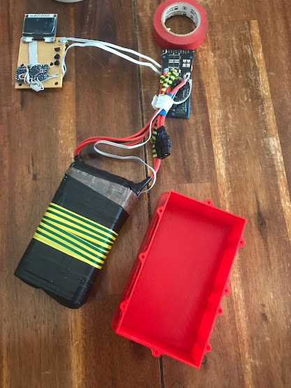
The result of the whole pack with the power circuit, the Arduino and Screen in the video below.
Create the 3D Printed case
To close the project, or at least the first prototype i need a case for embeded the parts togethers.
For this task my good friend Fusion360 and my trusty Pusa I3 will help me !

Result
As you can see i also added a XT60 connector on the board to drive device like mi iron solder. 😋

10 réponses
Very nice, very clean solution.
I have my custom design pcb based on bq30z55. Ordered bq30z55 chips from aliexpress and they became fresh thats why i need firmware for it. Firmware is not public by TI. By any chance could you backup firmware and share with me? I can share my pcb design pictures if you want.
Thanks in advance Ludovic.
Good job, mate 🙂
Bonsoir.
Puis-je utiliser l’interface FX2LP ?
DJI Battery Killer reconnaît-il l’interface FX2LP ?
Merci.
Cordialement.
Sir kindly guide me the hex values for 2500 mah and 4200mah
Also what value should I put in no. 19 design voltage so that the controller stops charging after 4.20 volts
I only have adruino is it possible to unseal and clear pf flags? and how?
Thank you
« Here after reading global infos and unsealing the chip i specificly read the 0x18 value known simply as 18 or DesignCapacity() .. The default value for my battery pack is 1915, this value represent the global capacity of the pack but not in common mAh representation but instead in bunch of 10mWh.. Quite uncommon yeah !? »
Design Capacity for BQ30Z55 represents the Capacity in mAh/2, because there is a resistor in BMS WM220 dividing the current. The declared value 1915 mAh is true while the output value is 3830 mAh.
Hi – can you please show what each battery terminal is in the Mavic Pro / Mavic Pro Platinum Battery pinouts – both batteries have same terminals?
I could not see this in your post and cannot find it listed on the internet. I specifically require to know which battery pins are SCL and SDA.
I have found which battery terminals are the RXD (UART receive – Pin 1) and TXD (UART TRANSMIT – Terminal 10) but do not know what pin number these correspond to; eg., which pin is SCL and which pin is SDA??
Greatly appreciate your help please. Please note, I can only read English text.
Best regards (from Australia), Ian
I found that there are no SCL and SDA pins on the connector.
I therefore had to open the battery, and on the backside of the control-board inside battery(under the foam pad) there are to small pads for SCL and SDA.
I soldered two wires to it, and was able to communicate with the BQ throug an arduino nano and an arduino UNO.
With the Circuitschools.com software.
I grounded the arduinos to pin 2 or 3 on either side of the connector.
Hello,
Thank you, I was able to detect my DJI Mavic Pro battery, but I don’t know how to reprogram it with Arduino. Have you improved a program with the DSA Smart Battery Arduino?
Sincerely,
Hello,
I can’t get the bq30z55 battery to be recognized with the DSA Smart Battery project. What should I do?
Sincerely,